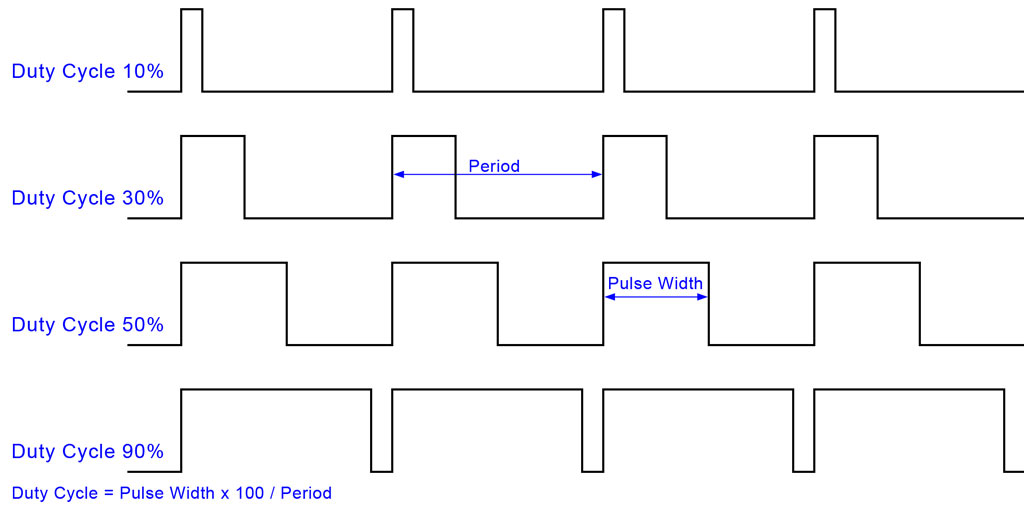
Motor control in any small electronic device be it an RC car, a small robot or an RC tractor is hevily reliant on pulse width modulation. When we want to control a motor we use a motor driver which normally consists of three control pins, two for direction and one to enable power to the motor. If we apply a constant voltage to the enable pin our motor will move at full speed. To give ourselve speed control we need to pulse the enable pin.
A motor is an inertial load as it trys to resist change i.e. it doesn’t want to accelerate or decelerate. We take advantage of this by quickly pulsing our enable pin. We give it a small pulse to spin the motor a little but the inertia of the motor carries it a little further until our next pulse comes, it decelerates slightly due to friction and the weight of the load it is carrying. We need to make sure the pulses are closely spaced so that the we can’t see the motor jerking. Increasing the width of the pulse increases the speed because the motor is being powered for longer and capable of overcoming the friction and weight of the load for longer.
The code below can be used with a motor driver chip to control a motor, pins 2 and 4 are for direction control and a pulse is generated on pin 3 for speed control.
I hope you found that useful and if you’ve any questions then shoot over to the RC Tractors Forum and I’ll do my best to answer them.


