- This topic has 17 replies, 2 voices, and was last updated 6 years, 5 months ago by
 VCR.
VCR.
- AuthorPosts
- March 5, 2017 at 3:31 am #3536
 modelleicherParticipant
Hello everybody,
Since I just got the controller and receiver working I thought I start this topic here. Not sure if its in the right place since it will also show off a tractor, but the tractor isn’t that interesting and just a guinea-pig I think its the right category.
I wanted to use the RCTractorGuy library at first, but since all of it is in the library and nothing in the sketch, and I don’t want to modify a library i don’t fully understand, I decided against it. I would have had to use the Basic Controller anyways, as i can not find a Pro Mini Mega, and all the displays and stuff is too much for me now. I just want to get a basic controller working.
This is a complete work in progress but the plan is to keep it simple.
Anyways, lets start with the Controller. I used a case from a IR helicopter because of the battery tray. Then I added a cheap switching regulator board to create 3.3V. The NRF24 and the Arduino both run off those 3.3V just fine even though the Arduino is a normal 5V Arduino.
So i’ve used a normal 5V Pro Mini, it is the cheapest one I could find (still has a Atmega168 chip) and cost only 1,45€.
Additionally, two joysticks, a 200µF capacitor, two pull-down resistors and a header for programming. Thats it (for now).


The PCB is made using the Toner Transfer method and Ferric Chloride.


I don’t plan on adding a display, but I will add 4 switches to select channels, another potentiometer and four buttons for lights or additional functions. With that, all the inputs on the Pro Mini are used. If i need more Buttons I can always add a second Pro Mini and connect via the serial port, but I think for the basic controller this is enough. I might build a more advanced version in the future, but for now that is more than I need.
Here is the current version of the code:
http://pastebin.com/iMgzh7JX/?e=1Nothing special, just the bare basics. But that is the whole point of this 😉 Feel free to use, modify, whatever obviously 🙂
Regards,
modelleicherMarch 5, 2017 at 4:36 am #3537modelleicherParticipantNow to the receiver part.
The receiver uses an Arduino Pro Mini, a NRF24 module and a small PCB on which the NRF24 module is mounted. Also a AMS1117 3.3V regulator and again a 200µF capacitor. I’m also using the TB6612FNG motor driver.
This setup is too big for smaller tractors, that is why I use a older model of mine to test it. I will show the model in detail later. It’s a Deutz Fahr D16006 I purpose-built for the use with Siku Control motors and electronics years ago after I stared at the parts graveyard of my previous Control tractors for too long one night. It was never finished (not painted, no details.. many issues.)
But back to the controller.


This Pro Mini has extra pins for pin 11,12 and 13 for the SPI bus. No idea why, but i like that. The wires are out of the way that way.

And here is the current code:
http://pastebin.com/rgki6yYXAgain, very basic and work in progress. And again, feel free to use, modify, whatever 🙂
The next thing to add (receiver and sender) is a adress system, buttons and pins for lights, maybe indicators.. Stuff like that. I also want to implement some basic inertia simulation so the tractor doesn’t launch like a racecar if you don’t touch the controls very carefully. The same for the steering, the little servo is just way too quick especially at 7.2V..
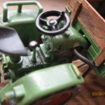
Now to the tractor. It is a Deutz D16006. The base is made of fine grained red beech wood. (Two reasons, first, we use it as firewood, second, its incredibly fine and sturdy hardwood, perfect for creating models) the details are made using Polystyrene. When I started the build I used to build everything out of wood. Nowadays I probably would use Polystyrene for the complete tractor, although it might be too light then. Anyways.. As I said, the tractor is not pretty and not finished. I just use it as a test vehicle for now.
So here is a before picture before I removed the Siku Control Electronics. As you can see, I used a standard servo. Then I brought the wires to the motor and the potentiometer out of it and soldered them to the PCB of a Siku Servo I placed in the front of the tractor. Worked perfect, and i didn’t have to use the stupid Siku servos.. But now with the Siku electronics completely gone its way way better 🙂


Here is a picture of the modified servo for the siku electronics, what a mess 🙂

Anyways, the Tractor completely without electronics

And here with the Receiver board test-fitted.. A lot of cleaning up wires to do still..


I also have a video from the very first test drive. Sorry for the horrible quality, I used the wrong setting on the camera.
Regards,
modelleicherMarch 8, 2017 at 2:17 pm #3542modelleicherParticipantHello,
Some progress has been made. I’ve added addresses to the whole thing. But i’ve also added some buttons..
Now, first i thought that i had enough pins, but then i realized that a few more buttons can’t be bad. So i thought about adding a second arduino. But as i have 4 free analog inputs that is not neccessary yet. Two of the free analog inputs i want to keep in case i need more potentiometers later on (i want to add at least one more).
But that leaves me with two analog inputs left.. Good for at least 12 Buttons.For now i am only using 6 buttons (5 in fact as i didn’t find a 6th one in my parts collection)
Anyways, i have added two small PCB’s to the controller, one for the address jumpers and one for the 6 pushbuttons.
Now, how do you get 6 pushbuttons on one arduino input? Its pretty simple, using two voltage dividers in series. Each one is a 75:25 divider which gives 4 different values depending on which button is pressed. Now you can add two more buttons pulling the input pin either high to vcc or low to ground. In total, 6 buttons.
Only drawback, you can’t press multiple buttons at the same time.Here is a scematic of this:

The resistor value doesn’t matter as long as it is above 1k and R1 & R3 have the same value and R2 and R4 are roughly double the value of R1. I didn’t have exactly double so the values in the shematic are what i used. If you have a different divide you have to adjust the values in the sketch to compensate.
Here is the sketch for the buttons in particular:
  // get 6 buttons from one analog pin using voltage dividers and analog read.
  anRead = analogRead(A7);

  if (anRead < 560 && anRead > 490) {
    raw_buttonByte2 = B00000000;
  }
  else if (anRead < 20) {
    raw_buttonByte2 = B00000001;
  }
  else if (anRead < 270 && anRead > 200) {
    raw_buttonByte2 = B00000010;
  }
  else if (anRead < 450 && anRead > 390) {
    raw_buttonByte2 = B00000100;
  }
  else if (anRead < 660 && anRead > 585) {
    raw_buttonByte2 = B00001000;
  }
  else if (anRead < 820 && anRead > 720) {
    raw_buttonByte2 = B00010000;
  }
  else if (anRead > 900) {
    raw_buttonByte2 = B00100000;
  }
As you can see, the analog value is read first, then we see in which range the analog value is.. And according to that we know which button is pressed.
Since the two voltage dividers are in symmetrie, when no button is pressed its always VCC / 2 or in analogRead values ~512 (since 1023 is VCC).
The best way to get the right values if you are using different resistor values is to just Serial.println(analogRead(analogPin)); and press each button and note the value. Then change the range values to fit those values.Anyways, here is the complete sketch of the sender at the moment:
http://pastebin.com/QUUYZL4CI have to do some cleanup in the sketch soon, add a few functions and put stuff from the main loop into functions.. But i want to document the process of the whole thing here.. Don’t know why but maybe somebodys is interested.. 😀
Here are a few pictures and a little description how i make my PCB’s in case somebody wants to know.
Instead of the usual iron method i hadn’t much luck with, i am using a wood stove.
The PCB lays on the hot surface face-up, heats up and then the paper is pressed on using a roller. It gets rolled and pressed for a few minutes and in each direction (the pressure is really what transfers the toner)

Once that is done i spray a bit of water on the hot PCB, it seems to seperate the paper from the toner better that way.
After that, it cools down and soaks for 10min in dish-soap water

The paper peels off very easily and cleanly and the toner is transfered perfectly.
Even though i have an old printer that has some dark and light spots.. With the iron method i always had some spots where
the toner just did not transfer properly on the light areas.

This is what it looks like after etching.

I use Ferric Chloride to etch, i guess its just personal preference. It can make a mess, but doesn’t require anything special but some sort of plastic or glass tray to etch in and gloves.Anyways, here are the finished new boards


And glued and soldered to the controller


At the moment i am using one of the buttons to switch between 3 max. drive speeds to allow for finer control.. (A detail i saw in the RCTractorGuy code and i really liked) but i want to use some seperate buttons or switches to do that at some point. The 6 buttons in the middle of the controller will be used for lights and turn lights and that stuff i guess.
But i am not even sure if i will use lights on my vehicles.. I hate having wires everywhere for the LED’s.. And although lights are extremely cool looking, they are not useful. In all the time “playing” with Siku Control i might have driven in a dark room maybe 4-5 times if at all. Usually i want to see the model drive.. So i don’t need any lights anyways. So i’m not sure yet.. Maybe just indicators and normal lights.. Not full worklight stuff.. We’ll see.Regards,
modelleicherMarch 19, 2017 at 4:36 pm #3543modelleicherParticipantHello,
Since the last time I’ve made some changes to the code. First of all, the Sender is now a bit updated. I have added some basic inertia simulation because with my 2S Lipo the tractor did launch and stop quite quickly, also the Servo reacts very apruptly now. (Its only supposed to get 7.2V max.. and the Siku Motors are made for a 1S Lipo)
Here is that part:
  // some very basic inertia simulation so the vehicle doesn't launch forward/backward and to limit the steering speed since the servo with a 2S Lipo is really fast
  // instead of the raw value the final value is sent to the vehicle. The final value is pretty much just a smoothed out version of the raw value. The higher the
  // difference between raw and final value is the faster the servo/motor accelerates
  // change the following two values to adjust, the lower the value the quicker the final value will follow the raw value.
  #define steeringInertiaValue 6;
  #define drivingInertialValue 9;
  // steering:
  if (raw_X >= final_X) // if the raw value is lower than the final value
  {
    int diff = raw_X - final_X; // get the difference between both values
    diff = diff / steeringInertiaValue; // the difference gets divided by the "inertia value"
    min(final_X = final_X + diff, raw_X); // now the difference is added to the final value

 }
  else if (raw_X <= final_X) // this is pretty much the same as the above just in the other direction
  {
    int diff = final_X - raw_X;
    diff = diff / steeringInertiaValue;
    max(final_X = final_X -diff, raw_X);

  }
  // driving:
  if (raw_RY >= final_RY)
  {
    int diff = raw_RY - final_RY;
    diff = diff / drivingInertialValue;
    min(final_RY = final_RY + diff, raw_RY);

 }
  else if (raw_RY <= final_RY)
  {
    int diff = final_RY - raw_RY;
    diff = diff / drivingInertialValue;
    max(final_RY = final_RY -diff, raw_RY);

  }
  //
There are also some Bugfixes, the speed selection works now as it’s supposed to.
The complete code:
http://pastebin.com/SiL8PBmGThere were also some changes to the tractor code. Headlights, battery voltage measurement and warning when the voltage reaches a low value for example. Also the address stuff works now.
Since I used a 2 cell Lipo I had to use a voltage divider for the battery voltage measurement as the Arduino can only take a maximum of 5V to its input pins. I’ve used a 75:25 voltage divider because my Arduino runs on the 3.3V regulator with the NRF24 module now, so the max. voltage I can supply to the Inputs is 3.3V. Therefor at 8.4V max voltage if the batterys are fully charged I get only 25% of that, ~2.1V, at the input pin.
Again, it doesn’t have to be absolutely acurate, I just use the analogRead function. The vehicle lights will start flashing at 6.6V left in the battery so I’m way above the dangerous discharge area of below 6V.. Just to keep the batterys safe 😉Here is the code for that:
void checkBatteryVoltage(int dt)
{
         // since LiPo cells can take damage or even explove if over-discharged we need to monitor the voltage
        // some LiPo cells come with protection circuits on the cell itself, but the cheap ones i use don't.
        // also most multiple cell lipos dont. I use a 2S Lipo in this tractor.
        // so we read the current battery voltage with analogRead and a voltage divider since the arduino runs on 3.3V and the LiPo fully charged has 8.4V
        // My Arduino runs on 3.27V usually, that means that our lower limit of 6.6V is reached at a analogRead value of 687
        // I did want to take the internal voltage into account but floating point math isn't that great on the arduino, and since i had a conservative number for the lower limit i think we'll be fine.
        // you need to change this whole thing if you are not running the arduino off of a 3.3V regulator!!!

        //batt_internalVCC = getVCCReading();

        batt_rawAnalogRead = analogRead(PIN_batt_readVcc);
        if (batt_rawAnalogRead <= 687)
        {
             Serial.println(batt_milisecondsLow);
            batt_milisecondsLow = batt_milisecondsLow + dt;
            if (batt_milisecondsLow > 1000) // battery is low for more than 1 second (to avoid shutting off on current spikes)
            {
                goBlinkLowBatteryLights(); // blink the lights really fast to show that the battery is empty
                batt_milisecondsLow = 0; // reset the battery low timer.. So the lights will start again after 1 second until battery is changed
            }
        }
        else
        {
            batt_milisecondsLow = 0;
        }
        //Serial.println(batt_rawAnalogRead);
}
I have also added all the output pins and the steering servo limits to the top of the sketch so they can be changed quickly without scanning through the sketch.
Here is the entire sketch as it is right now:
http://pastebin.com/0ZiLr9knAs always feel free to use and modify or do whatever with the code. But now that we are dealing with battery stuff, use at your own risk of course, I have not testet the sketch enough to feel comfortable to guarantee anything 😉
Hope whoever is reading this has a nice day 🙂
modelleicherMarch 29, 2017 at 12:46 pm #3546VCRParticipantThanks for sharing this project. I’ll see it very carefully. I’m trying to build an 1/24 scale R/C and this controller seems to be prefect
March 29, 2017 at 9:27 pm #3547VCRParticipantI am not an expert in the subject but I will try to make a clone. Do you have any circuit schematics that you can share?
March 31, 2017 at 7:13 pm #3548modelleicherParticipantHi,
I have the PCB Layout in Fritzing, I don’t have any shematics. But I can draw some, its pretty straight forward not much to it neither the sender nor the receiver are complicated.
March 31, 2017 at 7:36 pm #3549VCRParticipantI already started the drawing to make the board but I’m having a hard time seeing the connections to the Arduino. You can see the drawing at this address:
https://drive.google.com/open?id=0BzmqDlmVPwLCRXlONHFJczA0NGc
Can you help me finish the drawing?
I would like to try to optimize the receiver board to function more as a shield for the Arduino.Thanks again for sharing the project
Vasco ReisApril 2, 2017 at 3:12 pm #3553modelleicherParticipantHi,
The NRF24 module connects to the Arduino as following:
NRF ———— Arduino
Pin 1 —GND— one of the GND pins
Pin 2 —3.3v– AMS1117 3.3V regulator
Pin 3 —CE — Pin 9
Pin 4 —CSN— Pin 10
Pin 5 —SCK— Pin 13
Pin 6 –MOSI— Pin 11
Pin 7 –MISO— Pin 12On the receiver:
Pin 3 on the Arduino –> PWMA on the TB6612FNG
Pin 4 on the Arduino –> AIN2 on the TB6612FNG
Pin 5 on the Arduino –> AIN1 on the TB6612FNGPin 7 on the Arduino –> steering servo signal
Pin 8 on the Arduino –> lights on/off (switching lights to ground)
Pin A0 on the Arduino –> Battery voltage reading, see the section in my previous post about the voltage divider to read battery voltage
The NRF24 pins are fixed, the other ones you can change around in the sketch, they are defined right in the header. You just need to make sure you use a PWM Pin for the motor PWM output. Although if you build in 1/24 scale you might use a proper speed controller instead of the TB6612FNG I guess so you might have to change that whole part anyways.
On the sender side:
Y Axis potentiometer –> A0 Arduino Input
X Axis potentiometer –> A1 Arduino Input
RY Axis potentiometer –> A2 Arduino Input
RX Axis potentiometer –> A3 Arduino InputJoystick Button1 –> Pin 2 Arduino Input
Joystick Button2 –> Pin 3 Arduino InputAdress Jumper/Switch 1 –> Pin 5 Arduino Input
Adress Jumper/Switch 2 –> Pin 6 Arduino Input
Adress Jumper/Switch 3 –> Pin 7 Arduino Input
Adress Jumper/Switch 4 –> Pin 8 Arduino Input6 Button Voltage Divider Input -> A7 Arduino Input
The sender code hasn’t the Input Pins defined in the header yet, you can still change them around. Aside the fact that the analog pins have to be analog pins there is nothing special going on.
Here are the schematics for the sender:

And for the receiver:

I hope I didn’t make any mistakes in the schematics..
April 2, 2017 at 7:40 pm #3554modelleicherParticipantSince I’m too stupid to find the “edit” button I can’t edit my last post.
Anyways, regarding the “shield” idea..
Here is the second version of my receiver. I don’t know if it works yet, I made it two or so weeks ago but didn’t test it yet. I tried to get it as small as possible, but it is still too big for my other tractor.


Its basically a sandwich, the pcb at the bottom, the arduino on top and the NRF module on top of that. I have no idea if there are any interference issues.. Don’t think so with 2.4Ghz but not sure. Also I haven’t found a place for the 200µF cap.. That I would need to solder on where ever I’d find room in the model. (Of which there isn’t any..)
This would be the PDF version of that I used for the etching. (its mirrored for toner-transfer)
https://www.file-upload.net/download-12414450/Mainboard2_etch_copper_bottom.pdf.htmlThis would be the PDF for the small PCB I used as a baseplate inside the tractor from the posts above. (also mirrored)
https://www.file-upload.net/download-12414451/NRF24Baseplate_etch_copper_bottom.pdf.htmlIf there is enough room in your model you could just make a receiver board with headers for the NRF module and the arduino so you can take it apart or change it around later.. I haven’t asked yet, what are you building? A tractor or something else? Just curious 😉
April 3, 2017 at 9:12 pm #3555VCRParticipantAgain, thanks for sharing all this work.
For a while I did slot-car races, though the track closed and I got stuck with some 1/32 and 1/24 material. I thought of converting some of my slots to RC but I did not find anything adapted to what I want, either it does not exist or it’s too expensive. As I do not want to do races with them the TB6612FNG serves perfectly and on the other hand with the arduino I can control the lights, blinkers, windscreen wiper … The objective is to create an accessible platform that allows to convert a slot or a plastic kit (car, truck, tractor, machine …) in RC in an affordable way. I opted for the 1:24 scale to have room to install FPV and because there is a lot available. As I’m not very good at electronics and programming I investigated and ended up coming here 🙂
As soon as I have a little time I will carefully study all the information you have made available. For now I will concentrate on the receiver.Regards, VCR
April 15, 2017 at 8:55 pm #3556VCRParticipantIt did not go very well. I do not think it will be possible to weld.
https://drive.google.com/open?id=0BzmqDlmVPwLCZ1RfRGsxRUtNX2M
April 16, 2017 at 9:31 am #3557modelleicherParticipantHello,
Indeed, all the traces around the through-holes are ripped off. If you are CNC milling the PCB maybe try drilling the holes first and then route the traces (if you didn’t already)
If you drilled first and then routed the traces maybe your bit has a lot of runout? Aside from the holes it doesn’t look bad, though.
Although I have all the tools here to try PCB milling I haven’t yet, since the etching worked fine for me so far, so I don’t really know what is going on 😉
April 16, 2017 at 9:48 am #3558VCRParticipantThank you modelleicher. I’m going to buy a new drill, maybe with a slightly lower diameter. I will also redesign the plate to have more copper around the holes.
CNC is an excellent tool for manufacturing small parts. I’m using an MF70 with Chinese electronics.
May 14, 2017 at 10:35 pm #3561modelleicherParticipantHello again,
It has been a while since my last post. I did not change anything to the code yet, but I’ve changed the tractor itself a bit so I thought I show some pictures 🙂


As you can see, it now has a conncetor for the serial port at the back (TX, GND and 3.3V) for an implement. Also the tail lights have been added. I decided not to add turn signals since I never use them anyways and I would have had to use smaller LED’s and I’m quite OK with the bigger ones.. Need to practice SMD soldering a bit more first.. 😉


I now have added the 2S Lipo in the front, so I can not use the entire hood for electronics anymore.. It is quite “full” in the tractor now. Good thing it is “finished” as far as I’m concerned, I won’t add any other electronics/features. Just make it look better.


@VCR, how did the smaller hole size go, did it work?Have a nice evening 🙂
modelleicher- This reply was modified 6 years, 11 months ago by modelleicher.
- This reply was modified 6 years, 11 months ago by
- AuthorPosts


You must be logged in to reply to this topic.