Forum Replies Created
- AuthorPosts
 RC Tractor GuyKeymaster
That is a tricky one. Does it make sense to you that it didn’t work at all with the analogRead in the if loop? I mean you take a reading at i=25 and send at i=99 then why did you not see a change? You are clearly a better programmer than me, I’ve no clue of actual c or c++ so I don’t 100% follow your code unfortunately.
Have you tried hooking the receive XBee to your computer and seeing how fast the data is arriving and whether it is what you would expect? Just to be sure the delay is in the controller code.
Your 4WD is just awesome, every video I think it is so cool. I can’t wait to see it in action.
September 8, 2015 at 4:44 pm in reply to: Rubbish characters in lcd display when powered by battery #1133RC Tractor GuyKeymasterYes I taught you might have been using less than 5V, I think I tried to power one from 3.3V a few years back and it didn’t initialize at all and someone told me they are pretty much 5V only. I was using a 7.4 Volt lipo through the Arduino Uno Vin pin to power the LCD shield before so that works if you have one of those.
RC Tractor GuyKeymasterSeptember 7, 2015 at 9:22 pm in reply to: Rubbish characters in lcd display when powered by battery #1129RC Tractor GuyKeymasterWhen you say you are powering it from the battery, what pins are you actually connecting to Vcc or Vin? Also what voltage is the battery? I’m just wondering if the voltage might be too low for the LCD as the Arduino could operate easily at 3.3V but the LCD might be struggling to recognise input voltages that low. Your FTDI cable would be giving a constant 5V on directly to the Vcc pin. Have you measured the voltage on the LCD Vcc pin when you are connected to the battery?
RC Tractor GuyKeymasterHere is the code for the Arduino in the cab of the JD 8360RT
/*
Generic RC Tractor Cab Code Version 2.0
This code was written by Oisin O'Conchubhair for the website www.rctractors.net
This is the generic code used to control homemade RC Tractors.
The code is intended to be used with an Arduino Pro Mini
Circuit diagram can be found ar www.rctractors.net
Pin Assignment
D0 Serial RX
D1 Serial TX
D2 Right Indicator
D3 Work Lights
D4 Right Beacon
D5
D6
D7 Left Beacon
D8 NRF24 CE
D9 Left Indicator
D10 NRF24 CSN
D11 NRF24 MOSI
D12 NRF24 MISO
D13 NRF24 SCK
A0
A1
A2 Not assigned
A3 Not assigned
A4 Not assigned
A5 Not assigned
*/

// This section describes the vehicle
byte ID1 = 0x4A; // Enter a four byte ID for the vehicle
byte ID2 = 0x44; // for example F936 for the Fendt 936 model
byte ID3 = 0x38; // would be ID1 = 0x46; ID2 = 0x39; ID3 = 0x33; ID4 = 0x36
byte ID4 = 0x33; // because asci character F is 46 in hexidecimal and so on

// Variables used in the program
int Active = 0; // Variable to determine if the tractor is in active
int left_ind = 0; // Variable indicating if the left indicator is currently on or off
int right_ind = 0; // Variable indicating if the right indicator is currently on or off
int Ind_Timer = 0; // Variable used to record the length of time the indicator is on for
int ind_timer2 = 0; // Variable used to record the beacon is on for
int beac_on = 0; // Variable indicating if the right indicator is currently on or off
int beac_timer = 0; // Variable used to record the length of time the indicator is on for
int ind_active = 0; // Variable set to show that indicator code should be running
int beacon_active = 0; // Variable set to show that indicator code should be running
int spots_on = 0; // Variable to idicate if the large spot lights are on
int Last_Data_Timer = 0;
int Beacon_Option=2;
int Beacon_Timer=0;
byte dat1 = 0x00; // Stores received byte
byte dat2 = 0x00; // Stores received byte
byte dat3 = 0x00; // Stores received byte
byte dat4 = 0x00; // Stores received byte
byte dat5 = 0x00; // Stores received byte
byte dat6 = 0x00; // Stores received byte
byte command_val = 0; // Stores the command value
byte Data_Val_1 = 0; // Stores the data value
byte Data_Val_2 = 0; // Stores the data value
byte Data_Val_3 = 0; // Stores the data value
byte Data_Val_4 = 0; // Stores the data value
byte Data_Val_5 = 0; // Stores the data value
byte Data_Val_6 = 0; // Stores the data value
byte Data_Val_7 = 0; // Stores the data value
byte Data_Val_8 = 0; // Stores the data value
byte Data_Val_9 = 0; // Stores the data value
byte Data_Val_10 = 0; // Stores the data value
byte Data_Val_11 = 0; // Stores the data value
byte Data_Val_12 = 0; // Stores the data value
byte Old_Data_Val_1 = 0; // Stores the data value
byte Old_Data_Val_2 = 0; // Stores the data value
byte Old_Data_Val_3 = 0; // Stores the data value
byte Old_Data_Val_4 = 0; // Stores the data value
byte Old_Data_Val_5 = 0; // Stores the data value
byte Old_Data_Val_6 = 0; // Stores the data value
byte Old_Data_Val_7 = 0; // Stores the data value
byte Old_Data_Val_8 = 0; // Stores the data value
int data = 0; // Variable to indicate serial data is available

uint8_t buf[16];

#include <SPI.h>
#include "RF24.h"

RF24 radio(8,10);

// Controller Addresses
const uint64_t Controller_1 = 0xE8E8F0F0E1LL;
const uint64_t Controller_2 = 0xE8E8F0F0E2LL;
void setup()
{
Serial.begin(9600);

pinMode(2, OUTPUT); // Right indicator
pinMode(3, OUTPUT); // Work lights
pinMode(4, OUTPUT); // Right Beacon
pinMode(7, OUTPUT); // Left Beacon
pinMode(9, OUTPUT); // Left indicator

radio.begin(); // Initialize the NRF24 Radio Module
radio.openReadingPipe(1,Controller_1); // Set Address of Controller 1
radio.openReadingPipe(2,Controller_2); // Set Address of Controller 2
radio.startListening(); // Start listening for commands from the controllers
}

void loop()
{
Data_Check();
Data_Loss_Check();
if(Active==1){
Update_Motors();
LED_Control();
Beacon_Control();
}
Ind_Control();
}

void Data_Check(){
if (radio.available())radio.read(buf, 16); {

// We recieved a string of ten bytes, four ID, one command and six data values but they may not be for this tractor
if (buf[0] == ID1 && buf[1] == ID2 && buf[2] == ID3 && buf[3] == ID4){ // Confirm that the correct vehicle ID has been recieved
Data_Val_1 = buf[4]; // Store the controller left joystick x value
Data_Val_2 = buf[5]; // Store the controller left joystick x value
Data_Val_3 = buf[6]; // Store the controller left joystick x value
Data_Val_4 = buf[7]; // Store the controller left joystick x value
Data_Val_5 = buf[8]; // Store the controller left joystick x value
Data_Val_6 = buf[9]; // Store the controller left joystick x value
Data_Val_7 = buf[10]; // Store the head lights state
Data_Val_8 = buf[11]; // Store the work lights state
Data_Val_9 = buf[12]; // Store the indicator state
Data_Val_10 = buf[13]; // Store the new data value
Data_Val_11 = buf[14]; // Store the new data value
Data_Val_12 = buf[15]; // Store the new data value

Last_Data_Timer = 10;
Active = 1;
}
}
}

void Update_Motors(){

if(Data_Val_1!=Old_Data_Val_1){
Serial.write(0x0A); // \n
Serial.write(0x01); // \n
Serial.write(Data_Val_1); // \n
Old_Data_Val_1=Data_Val_1;
}

if(Data_Val_2!=Old_Data_Val_2){
Serial.write(0x0A); // \n
Serial.write(0x02); // \n
Serial.write(Data_Val_2); // \n
Old_Data_Val_2=Data_Val_2;
}

if(Data_Val_3!=Old_Data_Val_3){
Serial.write(0x0A); // \n
Serial.write(0x03); // \n
Serial.write(Data_Val_3); // \n
Old_Data_Val_3=Data_Val_3;
}

if(Data_Val_4!=Old_Data_Val_4){
Serial.write(0x0A); // \n
Serial.write(0x04); // \n
Serial.write(Data_Val_4); // \n
Old_Data_Val_4=Data_Val_4;
}

if(Data_Val_5!=Old_Data_Val_5){
Serial.write(0x0A); // \n
Serial.write(0x05); // \n
Serial.write(Data_Val_5); // \n
Old_Data_Val_5=Data_Val_5;
}

if(Data_Val_6!=Old_Data_Val_6){
Serial.write(0x06); // \n
Serial.write(0x01); // \n
Serial.write(Data_Val_6); // \n
Old_Data_Val_6=Data_Val_6;
}
}

void LED_Control(){
if(Data_Val_8!=Old_Data_Val_8){
if(Data_Val_8 == 1){ // Work Lights
digitalWrite(3, HIGH); // turn it on
Serial.write(0x0A); // \n
Serial.write(0x08); // \n
Serial.write(0x01); // \n
}
else{
digitalWrite(3, LOW); // turn it on
Serial.write(0x0A); // \n
Serial.write(0x08); // \n
Serial.write(0x00); // \n
}
Old_Data_Val_8=Data_Val_8;
}

if(Data_Val_7!=Old_Data_Val_7){
if(Data_Val_7 == 1){
Serial.write(0x0A); // \n
Serial.write(0x07); // \n
Serial.write(0x01); // \n
}
else if(Data_Val_7 == 2){
Serial.write(0x0A); // \n
Serial.write(0x07); // \n
Serial.write(0x02); // \n
}
else{
Serial.write(0x0A); // \n
Serial.write(0x07); // \n
Serial.write(0x00); // \n
}
Old_Data_Val_7=Data_Val_7;
}
}

void Ind_Control(){

Ind_Timer = Ind_Timer+1;

if(Ind_Timer = 2000){
if (Data_Val_9 == 1){
ind_left();
}
else if(Data_Val_9 == 2){
ind_right();
}
else if(Data_Val_9 == 3){
ind_hazard();
}
else{
ind_off();
}
Ind_Timer = 0;
}
}

// Indicator control functions
void ind_left(){
if (left_ind == 0){ // If left indicator is off
digitalWrite(2, HIGH); // turn it on
Serial.write(0x0A); // \n
Serial.write(0x09); // \n
Serial.write(0x02); // \n
left_ind = 1;

}
else{ // If left indicator is on
ind_off();
}
}

void ind_right(){
if (right_ind == 0){ // If right indicator is off
digitalWrite(9, HIGH); // turn it on
Serial.write(0x0A); // \n
Serial.write(0x09); // \n
Serial.write(0x01); // \n
right_ind = 1;
}
else{ // If right indicator is on
ind_off();
}
}

void ind_hazard(){
if (left_ind == 0){ // If hazards are off
digitalWrite(2, HIGH); // turn them on
digitalWrite(9, HIGH);
Serial.write(0x0A); // \n
Serial.write(0x09); // \n
Serial.write(0x03); // \n
left_ind = 1;
}
else{ // If hazards are on
ind_off();
}
}

void ind_off(){
digitalWrite(2, LOW); // turn them off
digitalWrite(9, LOW);
Serial.write(0x0A); // \n
Serial.write(0x09); // \n
Serial.write(0x00); // \n
left_ind = 0;
right_ind = 0;
}

void Beacon_Control(){
if(Beacon_Option==1){
Beacon_Timer++;
if (Beacon_Timer == 4){
digitalWrite(4, LOW);
digitalWrite(7, HIGH);
}
else if (Beacon_Timer == 8){
digitalWrite(4, HIGH);
digitalWrite(7, LOW);
Beacon_Timer = 0;
}
}
else if(Beacon_Option==2){
Beacon_Timer++;
if (Beacon_Timer == 4){
digitalWrite(4, HIGH);
}
if (Beacon_Timer == 6){
digitalWrite(4, LOW);
}
if (Beacon_Timer == 8){
digitalWrite(4, HIGH);
}
if (Beacon_Timer == 10){
digitalWrite(4, LOW);
}

if (Beacon_Timer == 14){
digitalWrite(7, HIGH);
}
if (Beacon_Timer == 16){
digitalWrite(7, LOW);
}
if (Beacon_Timer == 18){
digitalWrite(7, HIGH);
}
if (Beacon_Timer == 20){
digitalWrite(7, LOW);
Beacon_Timer = 0;
}
}
else{
digitalWrite(4, LOW);
digitalWrite(7, LOW);
}
}

void Data_Loss_Check(){
if(Last_Data_Timer != 0){
Last_Data_Timer = Last_Data_Timer - 1;
}

if(Last_Data_Timer == 0 && Active == 1){
Active = 0;
Data_Val_9 == 3;
Beacon_Option=0;
LED_Control();
Beacon_Control();
}
}
And the code for the Arduino in the body is:
/* Generic RC Tractor Body Code Version 2.0 This code was written by Oisin O'Conchubhair for the website www.rctractors.net This is the generic code used to control homemade RC Tractors. The code is intended to be used with an Arduino Pro Mini Circuit diagram can be found ar www.rctractors.net Pin Assignment D0 Serial RX D1 Serial TX D2 Left Indicator D3 Head Lights D4 Right Indicator D5 Drive Motor Speed Control D6 Brake Lights D7 Drive Motor Direction Control 1 D8 Drive Motor Direction Control 2 D9 Three-Point Linkage Servo Signal D10 Steering Servo Signal D11 Accessory Servo Signal D12 Accessory Serial TX Signal D13 Spot Lights A0 Beacon 1 A1 Beacon 2 A2 Not assigned A3 Not assigned A4 Not assigned A5 Not assigned */ // This section describes the vehicle byte ID1 = 0x4A; // Enter a four byte ID for the vehicle byte ID2 = 0x44; // for example F936 for the Fendt 936 model byte ID3 = 0x38; // would be ID1 = 0x46; ID2 = 0x39; ID3 = 0x33; ID4 = 0x36 byte ID4 = 0x33; // because asci character F is 46 in hexidecimal and so on byte steering_center = 0x52; // Every model is different so once we have biult the model byte steering_min = 0x40; // we test for the limits of the steering. Servo values must byte steering_max = 0x80; // not exceed 0xB4 as this is 180 degrees, max servo rotation byte drive_center = 128; // The drive is generally going to be the same for all models byte drive_max = 255; // but you can change these values if you need to byte drive_min = 0; byte link_center = 0x5A; // The link values depend your use. If used to control one of byte link_min = 0x40; // the three-point links, adjust the values. If used for an byte link_max = 0x80; // accessory, dont change values and use like external servo byte external_center = 0x5A; // Set a center value for the extra servos, 5A is 90 in Hex byte ex_ser_val = 30; // Variables used in the program int left_ind = 0; // Variable indicating if the left indicator is currently on or off int right_ind = 0; // Variable indicating if the right indicator is currently on or off int ind_timer = 0; // Variable used to record the length of time the indicator is on for int ind_timer2 = 0; // Variable used to record the beacon is on for int beac_on = 0; // Variable indicating if the right indicator is currently on or off int beac_timer = 0; // Variable used to record the length of time the indicator is on for int ind_active = 0; // Variable set to show that indicator code should be running int beacon_active = 0; // Variable set to show that indicator code should be running int dips_on = 0; // Variable to idicate if the dipped headlights are on int heads_on = 0; // Variable to idicate if the full beams are on int spots_on = 0; // Variable to idicate if the large spot lights are on int move1 = 125; // Variable used to determine the motor direction int move2 = 125; byte command_val = 0x00; // Stores the command value byte data_val = 0x00; // Stores the data value byte servo_val = 0x00; // Variable used to ensure data_val is between servo limits byte drive_val = 0x00; byte dat1 = 0x00; // Stores received byte byte dat2 = 0x00; // Stores received byte byte dat3 = 0x00; // Stores received byte byte dat4 = 0x00; // Stores received byte byte dat5 = 0x00; // Stores received byte byte dat6 = 0x00; // Stores received byte byte steering_val = 0x00; int link_ser_val = 127; // Battery Voltage Measurement Code //long readVcc() { // long result; // // Read 1.1V reference against AVcc // ADMUX = _BV(REFS0) | _BV(MUX3) | _BV(MUX2) | _BV(MUX1); // delay(2); // Wait for Vref to settle // ADCSRA |= _BV(ADSC); // Convert // while (bit_is_set(ADCSRA,ADSC)); // result = ADCL; // result |= ADCH<<8; // result = 1125300L / result; // Back-calculate AVcc in mV // return result; //} #include <Servo.h> // Include the library for controlling servos #include <SendOnlySoftwareSerial.h> // Include the library for creating additional serial ports SendOnlySoftwareSerial ExternalSerial(12); // Set pin 2 as RX and 7 as TX for the software serial port Servo link_servo; // Create servo object to control the link servo Servo external_servo; // Create servo object to control the external servo int data = 0; // Variable to indicate serial data is available void setup() { Serial.begin(9600); // Initialize main serial communication ExternalSerial.begin(9600); // Initialize additional serial communication // Set pins as outputs pinMode(2, OUTPUT); // Left indicator pinMode(3, OUTPUT); // Head lights pinMode(4, OUTPUT); // Right indicator pinMode(5, OUTPUT); // Drive motor 1 PWM control pin pinMode(6, OUTPUT); // Drive motor 2 PWM control pin pinMode(7, OUTPUT); // Drive motor 1 direction control 1 pinMode(8, OUTPUT); // Drive motor 1 direction control 2 pinMode(10, OUTPUT); // Brake Lights pinMode(13, OUTPUT); // Spot Lights pinMode(A0, OUTPUT); // Drive motor 2 direction control 1 pinMode(A1, OUTPUT); // Drive motor 2 direction control 2 pinMode(A2, OUTPUT); // Not assigned pinMode(A3, OUTPUT); // Not assigned pinMode(A4, OUTPUT); // Not assigned pinMode(A5, OUTPUT); // Not assigned // Set servo pins link_servo.attach(9); // attaches the servo on pin 9 to the link servo object external_servo.attach(11); // attaches the servo on pin 11 to the external servo object // Initialise the servos link_servo.write(link_center); // sets the initial link servo position external_servo.write(external_center); // sets the initial external servo position } // Main loop, this constantly repeats void loop() { if (Serial.available()) { // Check if serial data is available dat1=Serial.read(); // If yes then read it if (dat1 == 0x0A){ // Check for 0A indicating the start of a command string data++; // If 0A recieved then make data = 1 while (data == 1){ // While data = 1 wait for the first command byte if (Serial.available()) { command_val=Serial.read(); // Once receieved store it in dat1 data++; // Increment data variable } } while (data == 2){ // While data = 2 wait for the second command byte if (Serial.available()) { data_val=Serial.read(); // Once receieved store it in dat2 data = 0; // When the final byte is recieved we exit these loops } } } } switch (command_val){ // Perform an action based on the recieved command case 0x00: { // No command exit command selection break; } case 0x01: // Left Joystick X { if(data_val > 0xCC){// && ex_ser_val<255) ex_ser_val = ex_ser_val +1; ExternalSerial.write(0x09); } else if(data_val < 0x40){// && ex_ser_val>0) ex_ser_val = ex_ser_val -1; ExternalSerial.write(0x08); } else{ ExternalSerial.write(0x0A); } external_servo.write(ex_ser_val); // Set the servo position according to the recieved value command_val = 0x00; // Clear command and data values data_val = 0x00; break; } case 0x02: // Left Joystick Y { drive_val = data_val;//drive_min, drive_max); // scale the data value for use with the motor update_motor(); command_val = 0x00; // Clear command and data values data_val = 0x00; break; } case 0x03: // Left Pot { // We will scale this value with the controller so it works for different implements link_servo.write(data_val); // Set the servo position according to the scaled value command_val = 0x00; // Clear command and data values data_val = 0x00; break; } case 0x04: // Right Joystick X { command_val = 0x00; // Clear command and data values data_val = 0x00; break; } case 0x05: // Right Joystick Y { steering_val = data_val; // Scale data_val to between steering_min and steering_max update_motor(); command_val = 0x00; // Clear command and data values data_val = 0x00; break; } case 0x06: // Right Pot { ExternalSerial.write(data_val); // Output serial command to the implement command_val = 0x00; // Clear command and data values data_val = 0x00; break; } case 0x07: // Head Lights { if (data_val == 1) { analogWrite(3, 127); digitalWrite(10, HIGH); } else if (data_val == 2) { analogWrite(3, 255); digitalWrite(10, HIGH); } else { analogWrite(3, 0); digitalWrite(10, LOW); } command_val = 0x00; // Clear command and data values data_val = 0x00; break; } case 0x08: // Left indicator { if (data_val == 1){ // If off turn on digitalWrite(13, HIGH); } else{ digitalWrite(13, LOW); } } case 0x09: // Left indicator { if (data_val == 1){ // If off turn on digitalWrite(2, HIGH); digitalWrite(4, LOW); } else if(data_val == 2){ digitalWrite(2, LOW); digitalWrite(4, HIGH); } else if(data_val == 3){ digitalWrite(2, HIGH); digitalWrite(4, HIGH); } else{ digitalWrite(2, LOW); digitalWrite(4, LOW); } } case 0x0B: // Not Implemented { command_val = 0x00; // Clear command and data values data_val = 0x00; break; } case 0x0C: // Link servo { command_val = 0x00; // Clear command and data values data_val = 0x00; break; } case 0x0D: // Not Implemented { command_val = 0x00; // Clear command and data values data_val = 0x00; break; } case 0x0E: // Not Implemented { command_val = 0x00; // Clear command and data values data_val = 0x00; break; } case 0x0F: // Not Implemented { command_val = 0x00; // Clear command and data values data_val = 0x00; break; } } } void update_motor(){ if (drive_val < 120){ // These if functions leave a buffer zone of 15 bits above and below the drive center value move1 = map(drive_val, 120, 0, 0,255);//drive_min, drive_max); // scale the data value for use with the motor analogWrite(5,move1); // Set the PWM vlue on pin 5 to move the motor digitalWrite(8, HIGH); // Set the direction with pins 7 and 8 digitalWrite(7, LOW); } else if (drive_val > 135){ move1 = map(drive_val, 135, 255, 0,255);//drive_min, drive_max); // scale the data value for use with the motor analogWrite(5,move1); // Set the PWM vlue on pin 5 to move the motor digitalWrite(7, HIGH); // Set the direction with pins 7 and 8 digitalWrite(8, LOW); } else{ move1=0; analogWrite(5,move1); // Set the PWM vlue on pin 5 to move the motor digitalWrite(8, LOW); // Set the direction with pins 7 and 8 digitalWrite(7, LOW); } if(steering_val < 120){ move2 = map(steering_val, 128, 0, 0,255);//drive_min, drive_max); // scale the data value for use with the motor analogWrite(6,move2); // Set the PWM vlue on pin 5 to move the motor digitalWrite(A1, LOW); // Set the direction with pins 7 and 8 digitalWrite(A0, HIGH); } else if(steering_val > 135){ move2 = map(steering_val, 128, 255, 0,255);//drive_min, drive_max); // scale the data value for use with the motor analogWrite(6,move2); // Set the PWM vlue on pin 5 to move the motor digitalWrite(A0, LOW); // Set the direction with pins 7 and 8 digitalWrite(A1, HIGH); } else{ move2=0; analogWrite(6,move2); // Set the PWM vlue on pin 5 to move the motor digitalWrite(A0, LOW); // Set the direction with pins 7 and 8 digitalWrite(A1, LOW); } } void Battery_Check(){ //Batt_Vol = readVcc(); //if(Batt_Vol<3600){ //shutdown //} }RC Tractor GuyKeymasterHere is the code for the Arduino in the cab of the RC Massey 8680:
/*
RC Massey 8680 Tractor Cab Code Version 2.0
This code was written by Oisin O'Conchubhair for the website www.rctractors.net
This is the generic code used to control homemade RC Tractors.
The code is intended to be used with an Arduino Pro Mini
Pin Assignment
D0 Serial RX
D1 Serial TX
D2 Right Indicator
D3 Front Work Lights
D4 Right Beacon
D5 Rear Work Lights
D6
D7 Left Beacon
D8 NRF24 CE
D9 Left Indicator
D10 NRF24 CSN
D11 NRF24 MOSI
D12 NRF24 MISO
D13 NRF24 SCK
A0 Head Lights
A1
A2 Not assigned
A3 Not assigned
A4 Not assigned
A5 Not assigned
*/

// This section describes the vehicle
byte ID1 = 0x4D; // Enter a four byte ID for the vehicle
byte ID2 = 0x38; // for example F936 for the Fendt 936 model
byte ID3 = 0x36; // would be ID1 = 0x46; ID2 = 0x39; ID3 = 0x33; ID4 = 0x36
byte ID4 = 0x38; // because asci character F is 46 in hexidecimal and so on

// Variables used in the program
int Active = 0; // Variable to determine if the tractor is in active
int left_ind = 0; // Variable indicating if the left indicator is currently on or off
int right_ind = 0; // Variable indicating if the right indicator is currently on or off
int Ind_Timer = 0; // Variable used to record the length of time the indicator is on for
int Ind_Timer2 = 0; // Variable used to record the beacon is on for
int beac_on = 0; // Variable indicating if the right indicator is currently on or off
int beac_timer = 0; // Variable used to record the length of time the indicator is on for
int ind_active = 0; // Variable set to show that indicator code should be running
int beacon_active = 0; // Variable set to show that indicator code should be running
int spots_on = 0; // Variable to idicate if the large spot lights are on
int Last_Data_Timer = 0;
int Beacon_Option=2;
int Beacon_Timer=0;
byte dat1 = 0x00; // Stores received byte
byte dat2 = 0x00; // Stores received byte
byte dat3 = 0x00; // Stores received byte
byte dat4 = 0x00; // Stores received byte
byte dat5 = 0x00; // Stores received byte
byte dat6 = 0x00; // Stores received byte
byte command_val = 0; // Stores the command value
byte Data_Val_1 = 0; // Stores the data value
byte Data_Val_2 = 0; // Stores the data value
byte Data_Val_3 = 0; // Stores the data value
byte Data_Val_4 = 0; // Stores the data value
byte Data_Val_5 = 0; // Stores the data value
byte Data_Val_6 = 0; // Stores the data value
byte Data_Val_7 = 0; // Stores the data value
byte Data_Val_8 = 0; // Stores the data value
byte Data_Val_9 = 0; // Stores the data value
byte Data_Val_10 = 0; // Stores the data value
byte Data_Val_11 = 0; // Stores the data value
byte Data_Val_12 = 0; // Stores the data value
byte Old_Data_Val_1 = 0; // Stores the data value
byte Old_Data_Val_2 = 0; // Stores the data value
byte Old_Data_Val_3 = 0; // Stores the data value
byte Old_Data_Val_4 = 0; // Stores the data value
byte Old_Data_Val_5 = 0; // Stores the data value
byte Old_Data_Val_6 = 0; // Stores the data value
byte Old_Data_Val_7 = 0; // Stores the data value
byte Old_Data_Val_8 = 0; // Stores the data value
int data = 0; // Variable to indicate serial data is available

uint8_t buf[16];

#include <SPI.h>
#include "RF24.h"

RF24 radio(8,10);

// Controller Address
const uint64_t Controller_1 = 0xE8E8F0F0E1LL;
const uint64_t Controller_2 = 0xE8E8F0F0E2LL;

void setup()
{
Serial.begin(9600);

pinMode(2, OUTPUT); // Right indicator
pinMode(3, OUTPUT); // Front Work lights
pinMode(4, OUTPUT); // Right Beacon
pinMode(5, OUTPUT); // Rear Work Lights
pinMode(7, OUTPUT); // Left Beacon
pinMode(9, OUTPUT); // Left indicator
pinMode(A0, OUTPUT); // Head Lights

radio.begin(); // Initialize the NRF24 Radio Module
radio.openReadingPipe(1,Controller_1); // Set Address of Controller 1
radio.openReadingPipe(2,Controller_2); // Set Address of Controller 2
radio.startListening(); // Start listening for commands from the controllers
}

void loop()
{
Data_Check();
Data_Loss_Check();
if(Active==1){
Update_Motors();
LED_Control();
Beacon_Control();
}
Ind_Control();
}

void Data_Check(){
if (radio.available())radio.read(buf, 16);{

// We recieved a string of ten bytes, four ID, one command and six data values but they may not be for this tractor
if (buf[0] == ID1 && buf[1] == ID2 && buf[2] == ID3 && buf[3] == ID4){ // Confirm that the correct vehicle ID has been recieved
Data_Val_1 = buf[4]; // Store the controller left joystick x value
Data_Val_2 = buf[5]; // Store the controller left joystick y value
Data_Val_3 = buf[6]; // Store the controller left pot value
Data_Val_4 = buf[7]; // Store the controller right joystick x value
Data_Val_5 = buf[8]; // Store the controller right joystick y value
Data_Val_6 = buf[9]; // Store the controller right pot value
Data_Val_7 = buf[10]; // Store the head lights state
Data_Val_8 = buf[11]; // Store the work lights state
Data_Val_9 = buf[12]; // Store the indicator state
Data_Val_10 = buf[13]; // Store the new data value
Data_Val_11 = buf[14]; // Store the new data value
Data_Val_12 = buf[15]; // Store the new data value

Last_Data_Timer = 10;
Active = 1;
}
}
}

void Update_Motors(){

if(Data_Val_1!=Old_Data_Val_1){
Serial.write(0x0A); // \n
Serial.write(0x01); // \n
Serial.write(Data_Val_1); // \n
Old_Data_Val_1=Data_Val_1;
}

if(Data_Val_2!=Old_Data_Val_2){
Serial.write(0x0A); // \n
Serial.write(0x02); // \n
Serial.write(Data_Val_2); // \n
Old_Data_Val_2=Data_Val_2;
}

if(Data_Val_3!=Old_Data_Val_3){
Serial.write(0x0A); // \n
Serial.write(0x03); // \n
Serial.write(Data_Val_3); // \n
Old_Data_Val_3=Data_Val_3;
}

if(Data_Val_4!=Old_Data_Val_4){
Serial.write(0x0A); // \n
Serial.write(0x04); // \n
Serial.write(Data_Val_4); // \n
Old_Data_Val_4=Data_Val_4;
}

if(Data_Val_5!=Old_Data_Val_5){
Serial.write(0x0A); // \n
Serial.write(0x05); // \n
Serial.write(Data_Val_5); // \n
Old_Data_Val_5=Data_Val_5;
}

if(Data_Val_6!=Old_Data_Val_6){
Serial.write(0x0A); // \n
Serial.write(0x06); // \n
Serial.write(Data_Val_6); // \n
Old_Data_Val_6=Data_Val_6;
}
}

void LED_Control(){
if(Data_Val_8!=Old_Data_Val_8){
if(Data_Val_8 == 1){ // Work Lights
digitalWrite(3, HIGH); // turn it on
digitalWrite(5, HIGH); // turn it on
Serial.write(0x0A); // \n
Serial.write(0x08); // \n
Serial.write(0x01); // \n
}
else{
digitalWrite(3, LOW); // turn it on
digitalWrite(5, LOW); // turn it on
Serial.write(0x0A); // \n
Serial.write(0x08); // \n
Serial.write(0x00); // \n
}
Old_Data_Val_8=Data_Val_8;
}

if(Data_Val_7!=Old_Data_Val_7){
if(Data_Val_7 == 1){
analogWrite(A0, 127);
Serial.write(0x0A); // \n
Serial.write(0x07); // \n
Serial.write(0x01); // \n
}
else if(Data_Val_7 == 2){
analogWrite(A0, 255);
Serial.write(0x0A); // \n
Serial.write(0x07); // \n
Serial.write(0x02); // \n
}
else{
analogWrite(A0, 0);
Serial.write(0x0A); // \n
Serial.write(0x07); // \n
Serial.write(0x00); // \n
}
Old_Data_Val_7=Data_Val_7;
}
}

void Ind_Control(){

Ind_Timer = Ind_Timer+1;
if (Ind_Timer == 6000 && Ind_Timer2 == 1){ // If the desired on time is reached

if (Data_Val_9 == 1){
ind_left();
}
else if(Data_Val_9 == 2){
ind_right();
}
else if(Data_Val_9 == 3){
ind_hazard();
}
else{
ind_off();
}
Ind_Timer = 0;
Ind_Timer2 = 0;
//}
}
else if (Ind_Timer == 6000 && Ind_Timer2 != 1){ // If the desired on time is reached
Ind_Timer = 0; // Clear ind_timer
Ind_Timer2 = Ind_Timer2+1; // Incrememt ind_timer2
}
}

// Indicator control functions
void ind_left(){
if (left_ind == 0){ // If left indicator is off
digitalWrite(2, HIGH); // turn it on
Serial.write(0x0A); // \n
Serial.write(0x09); // \n
Serial.write(0x02); // \n
left_ind = 1;

}
else{ // If left indicator is on
ind_off();
}
}

void ind_right(){
if (right_ind == 0){ // If right indicator is off
digitalWrite(9, HIGH); // turn it on
Serial.write(0x0A); // \n
Serial.write(0x09); // \n
Serial.write(0x01); // \n
right_ind = 1;
}
else{ // If right indicator is on
ind_off();
}
}

void ind_hazard(){
if (left_ind == 0){ // If hazards are off
digitalWrite(2, HIGH); // turn them on
digitalWrite(9, HIGH);
Serial.write(0x0A); // \n
Serial.write(0x09); // \n
Serial.write(0x03); // \n
left_ind = 1;
}
else{ // If hazards are on
ind_off();
}
}

void ind_off(){
digitalWrite(2, LOW); // turn them off
digitalWrite(9, LOW);
Serial.write(0x0A); // \n
Serial.write(0x09); // \n
Serial.write(0x00); // \n
left_ind = 0;
right_ind = 0;
}

void Beacon_Control(){
if(Beacon_Option==1){
Beacon_Timer++;
if (Beacon_Timer == 40){
digitalWrite(4, LOW);
digitalWrite(7, HIGH);
}
else if (Beacon_Timer == 80){
digitalWrite(4, HIGH);
digitalWrite(7, LOW);
Beacon_Timer = 0;
}
}
else if(Beacon_Option==2){
Beacon_Timer++;
if (Beacon_Timer == 20){
digitalWrite(4, HIGH);
}
if (Beacon_Timer == 30){
digitalWrite(4, LOW);
}
if (Beacon_Timer == 40){
digitalWrite(4, HIGH);
}
if (Beacon_Timer == 50){
digitalWrite(4, LOW);
}

if (Beacon_Timer == 70){
digitalWrite(7, HIGH);
}
if (Beacon_Timer == 80){
digitalWrite(7, LOW);
}
if (Beacon_Timer == 90){
digitalWrite(7, HIGH);
}
if (Beacon_Timer == 100){
digitalWrite(7, LOW);
Beacon_Timer = 0;
}
}
else{
digitalWrite(4, LOW);
digitalWrite(7, LOW);
}
}

void Data_Loss_Check(){
if(Last_Data_Timer != 0){
Last_Data_Timer = Last_Data_Timer - 1;
}

if(Last_Data_Timer == 0 && Active == 1){
Active = 0;
Data_Val_9 == 3;
//Beacon_Option=0;
LED_Control();
Beacon_Control();
}
}
and here is the code for Arduino in the body of the tractor:
/* RC Massey 8680 Tractor Body Code Version 2.0 This code was written by Oisin O'Conchubhair for the website www.rctractors.net This is the generic code used to control homemade RC Tractors. The code is intended to be used with an Arduino Pro Mini Pin Assignment D0 Serial RX D1 Serial TX D2 Left Indicator D3 Head Lights D4 Right Indicator D5 Drive Motor Speed Control D6 Brake Lights D7 Drive Motor Direction Control 1 D8 Drive Motor Direction Control 2 D9 Three-Point Linkage Servo Signal D10 Steering Servo Signal D11 Accessory Servo Signal D12 Accessory Serial TX Signal D13 Spot Lights A0 Beacon 1 A1 Beacon 2 A2 Not assigned A3 Not assigned A4 Not assigned A5 Not assigned */ // This section describes the vehicle byte ID1 = 0x4D; // Enter a four byte ID for the vehicle byte ID2 = 0x38; // for example F936 for the Fendt 936 model byte ID3 = 0x36; // would be ID1 = 0x46; ID2 = 0x39; ID3 = 0x33; ID4 = 0x36 byte ID4 = 0x38; // because asci character F is 46 in hexidecimal and so on byte steering_center = 0x52; // Every model is different so once we have biult the model byte steering_min = 0x05; // we test for the limits of the steering. Servo values must byte steering_max = 0x95; // not exceed 0xB4 as this is 180 degrees, max servo rotation byte drive_center = 128; // The drive is generally going to be the same for all models byte drive_max = 255; // but you can change these values if you need to byte drive_min = 0; byte link_center = 0x5A; // The link values depend your use. If used to control one of byte link_min = 0x40; // the three-point links, adjust the values. If used for an byte link_max = 0x80; // accessory, dont change values and use like external servo byte external_center = 0x5A; // Set a center value for the extra servos, 5A is 90 in Hex byte ex_ser_val = 30; // Variables used in the program int left_ind = 0; // Variable indicating if the left indicator is currently on or off int right_ind = 0; // Variable indicating if the right indicator is currently on or off int ind_timer = 0; // Variable used to record the length of time the indicator is on for int ind_timer2 = 0; // Variable used to record the beacon is on for int beac_on = 0; // Variable indicating if the right indicator is currently on or off int beac_timer = 0; // Variable used to record the length of time the indicator is on for int ind_active = 0; // Variable set to show that indicator code should be running int beacon_active = 0; // Variable set to show that indicator code should be running int dips_on = 0; // Variable to idicate if the dipped headlights are on int heads_on = 0; // Variable to idicate if the full beams are on int spots_on = 0; // Variable to idicate if the large spot lights are on int move1 = 125; // Variable used to determine the motor direction int move2 = 125; byte command_val = 0x00; // Stores the command value byte data_val = 0x00; // Stores the data value byte servo_val = 0x00; // Variable used to ensure data_val is between servo limits byte drive_val = 0x00; byte dat1 = 0x00; // Stores received byte byte dat2 = 0x00; // Stores received byte byte dat3 = 0x00; // Stores received byte byte dat4 = 0x00; // Stores received byte byte dat5 = 0x00; // Stores received byte byte dat6 = 0x00; // Stores received byte byte steering_val = 0x00; int link_ser_val = 127; // Battery Voltage Measurement Code //long readVcc() { // long result; // // Read 1.1V reference against AVcc // ADMUX = _BV(REFS0) | _BV(MUX3) | _BV(MUX2) | _BV(MUX1); // delay(2); // Wait for Vref to settle // ADCSRA |= _BV(ADSC); // Convert // while (bit_is_set(ADCSRA,ADSC)); // result = ADCL; // result |= ADCH<<8; // result = 1125300L / result; // Back-calculate AVcc in mV // return result; //} #include <Servo.h> // Include the library for controlling servos #include <SendOnlySoftwareSerial.h> // Include the library for creating additional serial ports SendOnlySoftwareSerial ExternalSerial(12); // Set pin 2 as RX and 7 as TX for the software serial port Servo steering_servo; // Create servo object to control the steering servo Servo link_servo; // Create servo object to control the link servo int data = 0; // Variable to indicate serial data is available void setup() { Serial.begin(9600); // Initialize main serial communication ExternalSerial.begin(9600); // Initialize additional serial communication // Set pins as outputs pinMode(2, OUTPUT); // Left indicator pinMode(3, OUTPUT); // Head lights pinMode(4, OUTPUT); // Right indicator pinMode(5, OUTPUT); // Drive motor 1 PWM control pin pinMode(6, OUTPUT); // Drive motor 2 PWM control pin pinMode(7, OUTPUT); // Drive motor 1 direction control 1 pinMode(8, OUTPUT); // Drive motor 1 direction control 2 pinMode(10, OUTPUT); // Brake Lights pinMode(13, OUTPUT); // Spot Lights pinMode(A0, OUTPUT); // Drive motor 2 direction control 1 pinMode(A1, OUTPUT); // Drive motor 2 direction control 2 pinMode(A2, OUTPUT); // Not assigned pinMode(A3, OUTPUT); // Not assigned pinMode(A4, OUTPUT); // Not assigned pinMode(A5, OUTPUT); // Not assigned // Set servo pins link_servo.attach(9); // attaches the servo on pin 9 to the link servo object steering_servo.attach(10); // attaches the servo on pin 10 to the steering servo object // Initialise the servos link_servo.write(link_center); // sets the initial link servo position } // Main loop, this constantly repeats void loop() { if (Serial.available()) { // Check if serial data is available dat1=Serial.read(); // If yes then read it if (dat1 == 0x0A){ // Check for 0A indicating the start of a command string data++; // If 0A recieved then make data = 1 while (data == 1){ // While data = 1 wait for the first command byte if (Serial.available()) { command_val=Serial.read(); // Once receieved store it in dat1 data++; // Increment data variable } } while (data == 2){ // While data = 2 wait for the second command byte if (Serial.available()) { data_val=Serial.read(); // Once receieved store it in dat2 data = 0; // When the final byte is recieved we exit these loops } } } } switch (command_val){ // Perform an action based on the recieved command case 0x00: { // No command exit command selection break; } case 0x01: // Left Joystick X { command_val = 0x00; // Clear command and data values data_val = 0x00; break; } case 0x02: // Left Joystick Y { drive_val = data_val;//drive_min, drive_max); // scale the data value for use with the motor update_motor(); command_val = 0x00; // Clear command and data values data_val = 0x00; break; } case 0x03: // Left Pot { // We will scale this value with the controller so it works for different implements link_servo.write(data_val); // Set the servo position according to the scaled value command_val = 0x00; // Clear command and data values data_val = 0x00; break; } case 0x04: // Right Joystick X { servo_val = map(data_val, 0x00, 0xFF, steering_min, steering_max); // Scale data_val to between steering_min and steering_max steering_servo.write(servo_val); // Set the servo position according to the scaled value command_val = 0x00; // Clear command and data values data_val = 0x00; break; } case 0x05: // Right Joystick Y { command_val = 0x00; // Clear command and data values data_val = 0x00; break; } case 0x06: // Right Pot { if(data_val > 0xCC){// && ex_ser_val<255) ExternalSerial.write(0x09); } else if(data_val < 0x40){// && ex_ser_val>0) ExternalSerial.write(0x08); } else{ ExternalSerial.write(0x0A); } command_val = 0x00; // Clear command and data values data_val = 0x00; break; } case 0x07: // Head lights { if (data_val == 1) { analogWrite(3, 127); analogWrite(6, 125); ExternalSerial.write(0x05); // Output serial command to the implement } else if (data_val == 2) { analogWrite(3, 255); analogWrite(6, 125); ExternalSerial.write(0x05); // Output serial command to the implement } else { analogWrite(3, 0); analogWrite(6, 0); ExternalSerial.write(0x07); // Output serial command to the implement } command_val = 0x00; // Clear command and data values data_val = 0x00; break; } case 0x08: // Left indicator { if (data_val == 1){ // If off turn on digitalWrite(13, HIGH); ExternalSerial.write(0x01); // Output serial command to the implement } else{ digitalWrite(13, LOW); ExternalSerial.write(0x04); // Output serial command to the implement } } case 0x09: { if (data_val == 1){ // If off turn on digitalWrite(2, HIGH); digitalWrite(4, LOW); ExternalSerial.write(0x01); // Output serial command to the implement } else if(data_val == 2){ digitalWrite(2, LOW); digitalWrite(4, HIGH); ExternalSerial.write(0x02); // Output serial command to the implement } else if(data_val == 3){ digitalWrite(2, HIGH); digitalWrite(4, HIGH); ExternalSerial.write(0x03); // Output serial command to the implement } else{ digitalWrite(2, LOW); digitalWrite(4, LOW); ExternalSerial.write(0x04); // Output serial command to the implement } } case 0x0B: // Not Implemented { command_val = 0x00; // Clear command and data values data_val = 0x00; break; } case 0x0C: // Link servo { if (dips_on == 0) // If dips are off turn on { analogWrite(3, 125); // Set headlight pwm to 50% analogWrite(6, 125); // Set taillight pwm to 50% dips_on = 1; } else // Or if dips are on turn off { analogWrite(3, 0); // Set headlight pwm to 50% analogWrite(10, 0); // Set taillight pwm to 50% dips_on = 0; heads_on = 0; } command_val = 0x00; // Clear command and data values data_val = 0x00; break; } case 0x0D: // Not Implemented { if (heads_on == 0) { analogWrite(3, 255); // Set headlight pwm to 100% analogWrite(10, 125); // Set taillight pwm to 50% heads_on = 1; } else { analogWrite(3, 0); // Set headlight pwm to 100% analogWrite(10, 0); // Set taillight pwm to 50% dips_on = 0; heads_on = 0; } command_val = 0x00; // Clear command and data values data_val = 0x00; break; } case 0x0E: // Not Implemented { command_val = 0x00; // Clear command and data values data_val = 0x00; break; } case 0x0F: // Not Implemented { command_val = 0x00; // Clear command and data values data_val = 0x00; break; } } } void update_motor(){ if (drive_val < 120){ // These if functions leave a buffer zone of 15 bits above and below the drive center value move1 = map(drive_val, 120, 0, 0,255);//drive_min, drive_max); // scale the data value for use with the motor analogWrite(5,move1); // Set the PWM vlue on pin 5 to move the motor digitalWrite(8, HIGH); // Set the direction with pins 7 and 8 digitalWrite(7, LOW); } else if (drive_val > 135){ move1 = map(drive_val, 135, 255, 0,255);//drive_min, drive_max); // scale the data value for use with the motor analogWrite(5,move1); // Set the PWM vlue on pin 5 to move the motor digitalWrite(7, HIGH); // Set the direction with pins 7 and 8 digitalWrite(8, LOW); } else{ move1=0; analogWrite(5,move1); // Set the PWM vlue on pin 5 to move the motor digitalWrite(8, LOW); // Set the direction with pins 7 and 8 digitalWrite(7, LOW); } } void Battery_Check(){ //Batt_Vol = readVcc(); //if(Batt_Vol<3600){ //shutdown //} }RC Tractor GuyKeymasterHere is the code for the basic RC controller
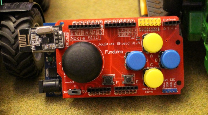
/* Basic Arduino Controller Code Version 1.0 This code was written by Oisin O'Conchubhair for the website www.rctractorguy.com The code is intended to be used with an Arduino Pro Uno with a joystick shield and NRF24L01 radio module */ // Define variables int Joy_X = 0x00; int Joy_Y = 0x00; int Joy_X_Old = 0x00; int Joy_Y_Old = 0x00; int Data_Check_Timer = 0; int Active_Vehicle = 0; int Num_Vehicle = 1; int Controller_Mode = 0; int A_Button = LOW; int B_Button = LOW; int C_Button = LOW; int D_Button = LOW; int E_Button = LOW; int F_Button = LOW; int Joy_Button = LOW; int X_Hold = 0; int Y_Hold = 0; #include <SPI.h> #include "RF24.h" RF24 radio(9,10); // Controller Address const uint64_t pipe = 0xE8E8F0F0E1LL; /*-----( Declare Variables )-----*/ uint8_t command[16]; // 2 element array of unsigned 8-bit type void setup() { pinMode(2, INPUT_PULLUP); // A Button pinMode(3, INPUT_PULLUP); // B Button pinMode(4, INPUT_PULLUP); // C Button pinMode(5, INPUT_PULLUP); // D Button pinMode(6, INPUT_PULLUP); // E Button pinMode(7, INPUT_PULLUP); // F Button pinMode(8, INPUT_PULLUP); // Joystick button radio.begin(); radio.openWritingPipe(pipe); } void loop() { Check_Vehicle_ID(); Check_Buttons(); Check_Pots(); Regular_Data_Check(); } void Check_Vehicle_ID(){ //Check which vehicle is active if(Active_Vehicle == 0){ command[0] = 0x4D; // M command[1] = 0x38; // 8 command[2] = 0x36; // 6 command[3] = 0x38; // 8 } else if(Active_Vehicle == 1){ command[0] = 0x4A; // J command[1] = 0x44; // D command[2] = 0x38; // 8 command[3] = 0x33; // 3 } } void Check_Buttons(){ // Check Joystick Switches A_Button = digitalRead(2); B_Button = digitalRead(3); C_Button = digitalRead(4); D_Button = digitalRead(5); E_Button = digitalRead(6); F_Button = digitalRead(7); Joy_Button = digitalRead(8); if (A_Button==LOW) { if (command[10] != 2){ command[10]=2; // Command to turn on head lights } else { command[10]=0; // Command to turn off head lights } // Wait for switch to be released while (A_Button == LOW) { A_Button = digitalRead(2); } Send_Data(); } if (C_Button==LOW) { if (command[11] != 1){ command[11]=1; // Command to turn on work lights } else { command[11]=0; // Command to turn off work lights } // Wait for switch to be released while (C_Button == LOW) { C_Button = digitalRead(4); } Send_Data(); } if (D_Button==LOW && B_Button==LOW) { if(command[12]!=3){ command[12]=3; // Turn on Hazard Lights } else{ command[12]=0; // Turn off Indicators } // Wait for switch to be released while (D_Button == LOW || B_Button==LOW) { B_Button = digitalRead(3); D_Button = digitalRead(5); } Send_Data(); } else if (B_Button==LOW) { if(Controller_Mode == 0){ if (command[12] != 1){ command[12]=1; // Command to turn on right indicator } else { command[12]=0; // Turn off Indicators } } else{ if(Y_Hold != 1){ Y_Hold = 1; } else{ Y_Hold = 0; } } // Wait for switch to be released while (B_Button == LOW) { B_Button = digitalRead(3); } Send_Data(); } else if (D_Button==LOW) { if(Controller_Mode == 0){ if (command[12] != 2){ command[12]=2; // Command to turn on left indicator } else { command[12]=0; // Turn off Indicators } } else{ if(X_Hold != 1){ X_Hold = 1; } else{ X_Hold = 0; } } // Wait for switch to be released while (D_Button == LOW) { D_Button = digitalRead(5); } Send_Data(); } if (E_Button==LOW) //E button cycles through controller modes { if(Controller_Mode != 1){ Controller_Mode = 1; //Enter accessory control mode } else{ Controller_Mode = 0; //Enter drive mode } // Wait for switch to be released while (E_Button == LOW) { E_Button = digitalRead(6); } Send_Data(); } if (F_Button==LOW) //F button cycles through vehicles { if(Active_Vehicle != Num_Vehicle){ Active_Vehicle = Active_Vehicle + 1; } else{ Active_Vehicle = 1; } // Wait for switch to be released while (F_Button == LOW) { F_Button = digitalRead(7); } Send_Data(); } if (Joy_Button==LOW) { // Function for joystick button goes here // Wait for switch to be released while (Joy_Button == LOW) { Joy_Button = digitalRead(8); } Send_Data(); } } void Check_Pots(){ Joy_X = analogRead(A0); Joy_X= map(Joy_X, 0, 1024, 0, 255); Joy_Y = analogRead(A1); Joy_Y= map(Joy_Y, 0, 1024, 0, 255); if(Joy_X != Joy_X_Old || Joy_Y != Joy_Y_Old){ if(Controller_Mode == 0){ command[5]=Joy_Y; command[7]=Joy_X; } else{ if(X_Hold == 0){ command[9]=Joy_X; } if(Y_Hold == 0){ command[6]=Joy_Y; } } Send_Data(); Joy_X_Old=Joy_X; Joy_Y_Old=Joy_Y; } } // Function to send the data void Send_Data(){ radio.write(command, sizeof(command)); Data_Check_Timer = 0; } // Send data in regular intervals to prevent tractor loosing control void Regular_Data_Check(){ Data_Check_Timer=Data_Check_Timer+1; if(Data_Check_Timer=1024){ Send_Data(); } }RC Tractor GuyKeymasterHere is a picture of the basic controller.
- This reply was modified 8 years, 8 months ago by RC Tractor Guy.
- This reply was modified 8 years, 8 months ago by
- AuthorPosts